What Is Flywheel Energy Storage and How Does It Work?
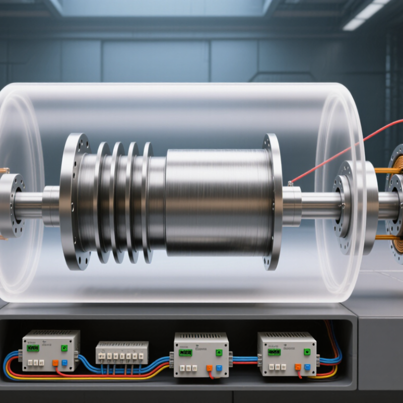
Flywheel Energy Storage stores electricity as rotational motion. A motor accelerates a heavy rotor; later, the spinning rotor drives a generator and returns electricity to the system. In a modern unit, the rotor spins inside a low-pressure enclosure, often supported by magnetic bearings. Picture a steel mass turning inside a sealed cylinder, with sensors constantly tracking its speed. Fast response. Short bursts. No combustion. These qualities make flywheels useful for frequency regulation, backup power, and applications requiring frequent charge-and-discharge cycles.
Performance depends on design and operating conditions. The U.S. Department of Energy’s Grid Energy Storage report describes flywheel systems as capable of roughly 85–90% round-trip efficiency, while emphasizing their strong power output and relatively short discharge duration. Those figures are technology-level estimates, not a guarantee for every installation. Keith Pullen, a researcher and coauthor of a widely cited review on flywheel storage, provides a useful engineering lens. A fair summary—not a verbatim quotation—of his published work is: “Flywheels are most valuable when rapid response and repeated cycling matter more than storing energy for many hours.” That distinction matters. A flywheel can respond quickly, but it is not automatically the best choice for long overnight storage.
Understanding the technology means looking beyond the rotor. Bearings, vacuum systems, power electronics, controls, and containment all shape efficiency, cost, and safety. Some claims simplify the story too much. The practical question is not whether a flywheel spins quickly, but whether its response, lifetime, and operating profile fit the job.
What Flywheel Energy Storage Is and Its Core Principle
Flywheel energy storage stores electricity as the motion of a spinning rotor. Inside a sturdy enclosure, a motor accelerates a heavy wheel or compact rotor to high speed. The faster it spins, the more energy it holds. In simplified form, stored energy depends on the rotor’s mass distribution and the square of its rotational speed. That squared relationship matters: a modest increase in speed can substantially increase stored energy.
When electricity is needed, the spinning rotor drives a generator, which converts its motion back into electrical power. The same machine may act as both motor and generator. Bearings support the rotor, while a low-pressure enclosure can reduce air resistance; the exact design varies. Some energy still escapes through friction, electrical resistance, and other losses. Nothing is perfectly sealed from loss.
The core principle is rotational inertia: a moving object resists changes to its motion. A familiar, small-scale example is a bicycle wheel that keeps turning after the rider stops pedaling. In an energy-storage system, controls manage charging and generator output, while the enclosure contains the rapidly rotating parts. Flywheels can respond quickly, but their stored energy may decline during extended standby. It is easy to focus on impressive spin speeds and overlook that practical trade-off.
Main Components of a Flywheel Energy Storage System
A flywheel energy storage system stores electricity as rotational energy inside a spinning rotor. Its main components work together: the rotor, bearings, motor-generator, enclosure, power electronics, and control sensors. The rotor, often a steel or composite cylinder, holds energy as it spins. Bearings support it; some designs use magnetic bearings to reduce contact and friction. A sealed enclosure limits air drag and helps contain debris if a rotor fails.
During charging, power electronics supply electricity to the motor-generator, which speeds up the rotor. During discharge, the rotor slows and drives the same machine as a generator. Sensors track speed, temperature, and vibration, while the controller adjusts power flow. That is the core. Small details matter. Bearing type, rotor material, and enclosure strength affect performance and maintenance. Still, a component list can hide difficult trade-offs: low friction does not mean zero energy loss.
Tips: Keep cooling paths clear, compare vibration readings with their normal baseline, and follow the system’s service schedule. A new hum deserves attention, even when output looks normal. Maintenance needs vary by design.
What Is Flywheel Energy Storage and How Does It Work?
This illustrative operating profile shows a 100 kW flywheel charging, entering standby, and then delivering power. Positive power represents charging; negative power represents discharge.
RotorStores energy as rotational kinetic energy in a rapidly spinning mass.
Motor-generatorUses electrical power to accelerate the rotor and generates electricity as it slows.
Bearings and enclosureSupport the rotor and help reduce friction and energy losses; many systems use a low-pressure enclosure.
Power electronicsControl the motor-generator and convert its output to electricity suitable for the connected system.
During charging, the motor-generator speeds up the rotor. During discharge, the rotor slows and drives the generator. Flywheels are commonly used for rapid-response power and short-duration energy storage.
How a Flywheel Stores Energy During Charging
During charging, a power converter sends electricity to a motor connected to the flywheel rotor. The motor applies torque, accelerating the rotor inside a protective enclosure. As it spins faster, the rotor stores more energy as rotational motion. Its energy depends on rotational inertia and the square of its speed. Small detail, big effect. Doubling rotational speed can store four times as much energy, assuming the same rotor.
The U.S. Department of Energy’s 2019 Energy Storage Technology and Cost Characterization Report models flywheel round-trip efficiency at about 85%. That figure covers both charging and discharging, not charging alone. During charging, some electricity becomes heat in the motor, bearings, and power electronics. Many systems reduce air resistance by operating in a low-pressure enclosure. Magnetic bearings can also reduce friction, though designs vary.
A practical system does not simply spin the rotor to its maximum speed every time. Its controls balance incoming power, safe operating limits, and the need to leave room for later charging. Sandia National Laboratories’ Electricity Storage Handbook describes flywheels as suited to frequent cycling and rapid power response. The picture is useful, but incomplete: real performance depends on system design and operating conditions. A brief grid fluctuation can trigger a quick charge, while longer energy storage requires a different approach.
What Is Flywheel Energy Storage and How Does It Work? - How a Flywheel Stores Energy During Charging
| Charging stage |
What happens |
Energy or operating principle |
Key detail |
| 1. Electrical input |
An external electrical supply provides power to the system. |
Electrical energy enters the motor-generator. |
Power electronics regulate the electrical input and control the machine. |
| 2. Motor operation |
The motor-generator operates as a motor and applies torque to the rotor. |
Electrical energy is converted into rotational mechanical energy. |
The rotor accelerates as the motor supplies torque. |
| 3. Rotor acceleration |
The flywheel rotor spins faster, storing energy in its rotation. |
Rotational energy: E = ½Iω². |
I is the rotor’s moment of inertia in kg·m²; ω is angular speed in rad/s. |
| 4. Stored-energy state |
The rotor continues spinning after charging power is reduced or stopped. |
Energy remains as kinetic energy in the rotating mass. |
A containment enclosure helps manage mechanical hazards; reduced air pressure can limit windage losses. |
| 5. Speed and energy control |
Control equipment monitors rotor speed and system conditions during charging. |
Because energy is proportional to the square of speed, E ∝ ω² for a fixed rotor. |
The permitted operating-speed range depends on rotor design and system limits. |
| 6. Charging losses |
Some input energy is dissipated during conversion and rotation. |
Losses can include electrical resistance, bearing friction, and aerodynamic drag. |
The amount of energy retained depends on system design and operating conditions. |
How Stored Energy Is Released and Converted to Electricity
When a flywheel delivers electricity, its spinning rotor slows down. The rotor’s kinetic energy passes through a shaft to a motor-generator, which switches roles and produces electrical current. Power electronics adjust that output to match the grid or a connected load. The response can be very fast, useful for brief power gaps and sudden changes in demand. It is not a long-duration energy source.
The U.S. Department of Energy’s 2019 Energy Storage Technology and Cost Characterization Report uses about 85% round-trip efficiency as a flywheel benchmark. In practical terms, some energy becomes heat in bearings, electrical components, and air resistance; the exact result depends on system design and operating conditions. The rotor may spin inside a vacuum enclosure to reduce drag. That is the elegant part—and the limitation: a flywheel can release power quickly, but its stored energy is usually suited to short bursts, not hours of supply. A benchmark is not a promise for every installation.
Tips: Check both power rating and discharge duration. A high power rating alone does not show how long the system can sustain output. Ask for measured efficiency at the intended operating speed and load.
Key Uses and Operating Limits of Flywheel Storage
Flywheel energy storage keeps energy as rotation inside a spinning rotor. A motor accelerates the rotor, then a generator converts its motion back into electricity when needed. These systems respond quickly, making them useful for smoothing brief power fluctuations, supporting frequency regulation, and bridging short interruptions. Fast response. They may also help stabilize facilities with sudden load changes, such as data centers or manufacturing equipment.
Their main operating limit is duration. A flywheel can deliver high power, but stored energy gradually falls as friction and electrical losses slow the rotor. Many installations are better suited to seconds or minutes of support than hours of backup. Capacity, rotor speed, and system design determine actual performance. The spinning assembly also requires a strong containment enclosure and careful maintenance. A practical concern is that short-duration performance can look impressive on paper, while long outages still need another energy source.
Tips: Match the system to the expected event: frequent, brief power dips differ from prolonged outages. Ask for both power and usable energy ratings, and check how performance changes over time. Leave room for uncertainty; real operating conditions rarely match a perfect test.